Desa CGB35P User Manual
Browse online or download User Manual for Space heaters Desa CGB35P. Desa CGB35P User's Manual
- Page / 40
- Table of contents
- BOOKMARKS
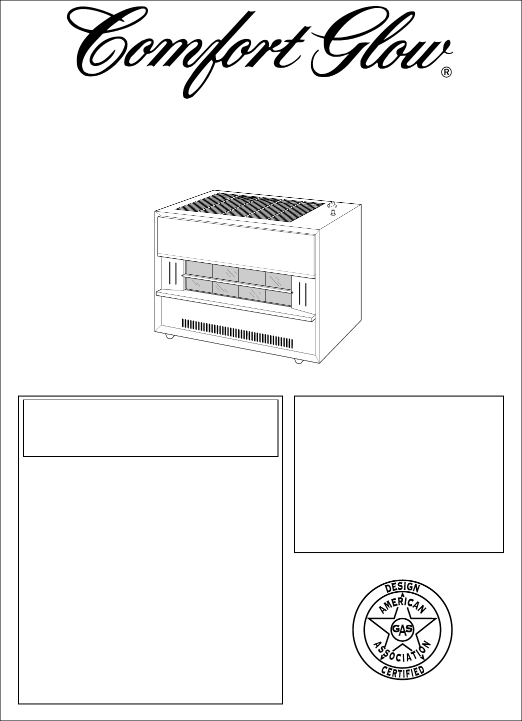
- VENTED PROPANE 1
- GAS HEATERS 1
- CONTENTS 2
- INFORMATION 3
- IDENTIFICATION 5
- WARNING 6
- INSTALLING 10
- FRESH AIR FOR 16
- COMBUSTION 16
- VENTILATION 16
- OPERATING 20
- PILOT AND 23
- INSPECTING 23
- CLEANING 25
- MAINTENANCE 25
- TROUBLE 26
- SHOOTING 26
- PROCEDURES 30
- TECHNICAL 33
- ORDERING 34
- REPLACEMENT 34
- CENTRALS 34
- ACCESSORIES 35
- ILLUSTRATED 36
- PARTS LIST 36
- Assembly 36
- WARRANTY INFORMATION 40
Summary of Contents
Save this manual for future reference.WARNING: If the information in this manualis not followed exactly, a fire or explosionmay result causing propert
10100352VENTING HEATER (continued)INSTALLINGHEATERContinuedProper Size VentTo safely vent heater, the vent connector pipe must be the same diameter as
11100352INSTALLINGHEATERContinuedCONNECTING TO GAS SUPPLYBULK PROPANETANKVENTExternal RegulatorVent Pointing DownThe installer must supply an external
12100352Figure 7 - Gas Connection* An A.G.A. design-certified manual shutoff valve with 1/8" NPT tap is anacceptable alternative to test gauge c
13100352INSTALLINGHEATERContinuedCHECKING GAS CONNECTIONSFigure 8 - Manual Shutoff ValvePOOn PositionOff PositionPressure Testing Gas Supply Piping Sy
14100352INSTALLINGHEATERContinuedINSTALLING GLASS PANEL1. Locate the glass panel package inside the back of the heater.WARNING ICON G 001 CAUTIONBefor
15100352INSTALLINGHEATERContinued21GlassPanelLower GlassRetainingChannelFigure 11 - Inserting Top Edge ofGlass Panel into Upper GlassRetaining Channel
16100352FRESH AIR FORCOMBUSTIONANDVENTILATION WARNINGThis heater must have fresh air for proper operation. Ifnot, poor fuel combustion and improper ve
17100352FRESH AIR FORCOMBUSTIONANDVENTILATIONContinuedDETERMINING FRESH-AIR FLOW FOR HEATER LOCATIONExample 1: Locating Heater in Unconfined (Open) Ar
18100352FRESH AIR FORCOMBUSTIONANDVENTILATIONContinuedDraft Hood Spillage: This is a hazardous situation. Draft hood spillage re-leases poisonous carb
19100352FRESH AIR FORCOMBUSTIONANDVENTILATIONContinuedVentilationGrills intoCloset forHot Water HeaterRecommendedFresh Air Ductinto Crawl Space inFurn
2100352CONTENTSSECTION PAGESafety Information...3Product Identification ...
20100352OPERATINGHEATERA. This appliance has a pilot which must be lighted by hand. When lighting thepilot, follow these instructions exactly.B. BEFOR
211003525. Wait five (5) minutes to clear out any gas. Then smell for gas, including near thefloor. If you smell gas, STOP! Follow “B” in the safety i
22100352MANUAL LIGHTING PROCEDURE1. Remove lower front access panel on heater.2. Locate pilot. Pilot is attached to the front of burner.3. Follow step
23100352INSPECTINGPILOT ANDBURNERFLAMECheck pilot flame pattern and burner flame pattern often.PILOT FLAME PATTERNFigure 18 shows a correct pilot flam
24100352INSPECTINGPILOT ANDBURNERFLAMEContinuedSharp BlueFlameHighYellowFlameFlameLiftingOff ofBurnerFigure 21 - Incorrect Burner Flame PatternsFigure
25100352CLEANINGANDMAINTENANCECABINETAir Passageways• Use a vacuum cleaner or pressurized air to clean.Exterior• Use a soft cloth dampened with a mild
26100352TROUBLE-SHOOTINGNote: All troubleshootingitems are listed in order ofoperation. WARNINGTurn off and unplug heater and let cool before servici
27100352TROUBLE-SHOOTINGContinuedOBSERVEDPROBLEMPilot lights but flamegoes out whencontrol knob isreleased.Burner does not lightafter pilot is lit.Del
28100352TROUBLE-SHOOTINGContinuedOBSERVEDPROBLEMBurner backfiringduring combustion.Yellow flame duringburner combustion.Slight smoke or odorduring ini
29100352 WARNINGTROUBLE-SHOOTINGContinuedIf you smell gas• Shut off gas supply.• Do not try to light any appliance.• Do not touch any electrical switc
3100352SAFETYINFORMATION WARNINGSIMPORTANT: Read this owner’s manual carefully and completely be-fore trying to assemble, operate, or service this hea
30100352SERVICEPROCEDURESRemoving Control Valveand Burner Tube1. Shut off gas supply toheater.2. Remove lower frontaccess panel on heater.3. Disconnec
31100352SERVICEPROCEDURESContinuedRemoving Burner1. Shut off gas supply toheater.2. Remove lower frontaccess panel on heater.3. Disconnect burner tube
32100352SERVICEPROCEDURESContinuedChanging Burner Orifice1. Shut off gas supply toheater.2. Remove lower frontaccess panel on heater.3. Disconnect bur
33100352TECHNICALSERVICEYou may have further questions about installation, operation, or troubleshooting.If so, contact DESA International’s Technical
34100352Note: Use only original replacement parts. This will protect your warranty cover-age for parts replaced under warranty.Parts Under WarrantyCon
35100352ACCESSORIESBLOWER KIT - PART NUMBER GA6010For all models. Provides better heat distribution.Makes heater more efficient. Complete installation
36100352ILLUSTRATEDPARTS LISTBurnerAssembly348101112567912131415161718192827 735 Model650 Model1124-2 202123 26 2217164 24 24-1 24-3 24-425 7
37100352This list contains replaceable parts used in your heater. When ordering parts, followthe instructions listed under Ordering Replacement Parts
38100352ILLUSTRATEDPARTS LISTCabinetAssemblyThis list contains replaceable parts used in your heater. When ordering parts, followthe instructions list
39100352NOTES_________________________________________________________________________________________________________________________________________
4100352SAFETYINFORMATIONContinued WARNINGS Continued7. Provide the following minimum heater clearances from combustibles (as viewedfrom the front of h
LIMITED WARRANTYCOMFORT GLOW VENTED PROPANE GAS HEATERSLIMITED ONE YEAR WARRANTYThis DESA product is warranted to the original purchaser to be free fr
5100352PRODUCTIDENTIFICATIONLower FrontAccess PanelFigure 1 - Vented Propane Gas HeaterDraft HoodOutlet forVentingSystemControlValveFigure 2 - Vented
6100352Install and use heater with care. Follow all local codes. In the absence of localcodes, use the latest edition of the following:• National Fuel
7100352INSTALLINGHEATERContinuedLOCATING HEATERWARNING ICON G 001 WARNINGMaintain the minimum clearances shown in Figure 3,below. If you can, provide
8100352Note: Venting/chimney materials are not supplied with heater.VENTING HEATERINSTALLINGHEATERContinued WARNINGThis heater has a vent safety shut-
9100352INSTALLINGHEATERContinuedVENTING HEATER (continued)WARNING ICON G 001 WARNINGDo not vent heater in any of the following ways (see Figure 4).He
Related products and manuals for Space heaters Desa CGB35P
 (14 pages)
(20 pages)
(36 pages)
(14 pages)
(20 pages)
(36 pages)
 (48 pages)
(26 pages)
(48 pages)
(26 pages)
 (56 pages)
(24 pages)
(24 pages)
(24 pages)
(20 pages)
(36 pages)
(32 pages)
(18 pages)
(14 pages)
(48 pages)
(16 pages)
(20 pages)
(20 pages)
(28 pages)
(28 pages)
(56 pages)
(24 pages)
(24 pages)
(24 pages)
(20 pages)
(36 pages)
(32 pages)
(18 pages)
(14 pages)
(48 pages)
(16 pages)
(20 pages)
(20 pages)
(28 pages)
(28 pages)
© 2020, manymanuals.com. All rights reserved. | 2.778 s |
 Manymanuals.com
 Manymanuals.de
 Manymanuals.fr
 Manymanuals.it
 Manymanuals.pl
 Manymanuals.cz
 Manymanuals.es
 Manymanuals-pt.com
Comments to this Manuals